Renault Clio: Front seat height adjuster control: Removal - Refitting
FRONT SEAT TYPE 02 or FRONT SEAT TYPE 03 or FRONT SEAT TYPE 05, and WITHOUT SPORT SEATS, and DOCUMENTATION PHASE 1 or DOCUMENTATION PHASE 2

REMOVAL
OPERATION FOR REMOVAL OF PART CONCERNED

- Unclip the trim of the front seat height adjustment control using the tool (Car. 1363).

- Remove:
- the front seat height adjustment control bolts (1),
- the front seat height adjustment control.
REFITTING
I - REFITTING OPERATION FOR PART CONCERNED
- Refit the front seat height adjustment control.
- Clip on the trim of the front seat height adjustment control.
II - FINAL OPERATION
- Carry out a function test.
Front seat lumbar adjustment: Removal - Refitting
FRONT SEAT TYPE 03 or FRONT SEAT TYPE 05, and WITHOUT SPORT SEATS, and DOCUMENTATION PHASE 2

IMPORTANT
Before beginning work on any component of the safety system, it is essential to lock the airbag computer using the Diagnostic tool (see Airbag and pretensioners: Precautions for the repair) (88C, Airbag and pretensioners). When this function is activated, all the trigger lines are inhibited and the airbag warning light on the instrument panel is continuously lit (with the ignition on).
IMPORTANT
Never handle the pyrotechnic systems (pretensioners or airbags) near to a source of heat or naked flame - they may be triggered.
REMOVAL
I - REMOVAL PREPARATION OPERATION
- Disconnect the battery (see Battery: Removal - Refitting) (80A, Battery).
- Remove:
- the front seat (see 75A, Front seat frames and mechanisms, Complete front seat: Removal - Refitting, 75A-33),
- the front seat headrest guides (see 79A, Seat accessories, Front seat headrest guide: Removal - Refitting, 79A-6),
- the front seatback " cover - foam " assembly (see 77A, Front seat trim, Front seatback trim: Removal - Refitting, 77A-13).
II - OPERATION FOR REMOVAL OF PART CONCERNED

Note: For this operation, the lumbar pad must be loose.
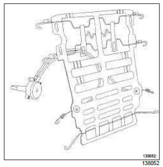
- Remove the bolt (1) from the front seat lumbar adjustment mechanism.
- Release the front seat lumbar adjustment mechanism.
1 - First fitting

- Unclip the front seat lumbar pad in the order shown.
2 - Second fitting

- Unclip the front seat lumbar pad in the order shown.

- Remove the " lumbar adjustment mechanism - lumbar pad " assembly.
Note: The Parts Department supplies the lumbar adjustment mechanism assembled with the lumbar pad.
REFITTING
I - REFITTING OPERATION FOR PART CONCERNED
- Refit the " lumbar adjustment mechanism - lumbar pad " assembly.

- Clip the lumbar pad onto the front seat
Note: The lumbar pad springs are positioned on the front seatback frame with the hook towards the rear
- Carry out a function test.
II - FINAL OPERATION
- Refit:
- the front seatback " cover - foam " assembly (see 77A, Front seat trim, Front seatback trim: Removal - Refitting, 77A-13),
- the front seat headrest guides (see 79A, Seat accessories, Front seat headrest guide: Removal - Refitting, 79A-6),
- the front seat (see 75A, Front seat frames and mechanisms, Complete front seat: Removal - Refitting, 75A-33).
- Connect the battery (see Battery: Removal - Refitting) (80A, Battery).
- Unlock the airbag computer using the Diagnostic tool (see Airbag and pretensioners: Precautions for the repair) (88C, Airbags and pretensioners).

