Renault Clio: K4J or K4M

REMOVAL
I - REMOVAL PREPARATION OPERATION
- Position the vehicle on a two-post lift (see Vehicle: Towing and lifting) (02A, Lifting equipment).
- Remove:
- the engine cover,
- the engine undertray bolts,
- the engine undertray,
- the front wheels (see Wheel: Removal - Refitting) (35A, Wheels and tyres),
- the front wheel arch liners (see Front wheel arch liner: Removal - Refitting) (55A, Exterior protection),
- the front bumper (see Front bumper: Removal - Refitting) (55A, Exterior protection).
- the battery (see Battery: Removal - Refitting) (80A, Battery),
- the battery tray (see ) (80A, Battery),
- the air filter unit (see 12A, Fuel mixture, Air filter: Removal - Refitting, 12A-15),
- the windscreen wiper arms (see Windscreen wiper arm: Removal - Refitting) (85A, Wiping - Washing),
- the scuttle panel grille (see Scuttle panel grille: Removal - Refitting) (56A, Exterior equipment),
- the scoop under the scuttle panel grille (see Scoop under the scuttle panel grille: Removal - Refitting) (56A, Exterior equipment).
- Drain the cooling system (see 19A, Cooling, Cooling system: Draining - Refilling, 19A-16).
- Remove:
- the ignition coils (see 17A, Ignition, Coils: Removal - Refitting, 17A-2),
- the throttle valve (see 12A, Fuel mixture, Throttle valve: Removal - Refitting, 12A-33),
- the intake distributor (see 12A, Fuel mixture, Inlet distributor: Removal - Refitting, 12A-45).
K4M, and 862
- Remove the oil separator (see 11A, Top and front of engine, Oil decanter: Removal - Refitting, 11A-302).
- Remove:
- the lower engine tie-bar (see 19D, Engine mounting, Lower engine tie-bar: Removal - Refitting, 19D-13),
- the right-hand suspended engine mounting (see 19D, Engine mounting, Right-hand suspended engine mounting: Removal - Refitting, 19D-22),
- the accessories belt (see 11A, Top and front of engine, Accessories belt: Removal - Refitting, 11A-5),
- the crankshaft accessories pulley (see 11A, Top and front of engine, Crankshaft accessories pulley: Removal - Refitting, 11A-31),
- the timing belt (see 11A, Top and front of engine, Timing belt: Removal - Refitting, 11A-48).

- Remove the nuts (1) from the exhaust flange.
- Disconnect the oxygen sensor connectors.
K4M, and 862
- Drain the gearbox (see Manual gearbox oils: Draining - Filling) (21A, Manual gearbox).
- Remove:
- the front right-hand wheel driveshaft (see Front right-hand driveshaft: Removal - Refitting) (29A, Driveshafts),
- the catalytic converter (see 19B, Exhaust, Catalytic converter: Removal - Refitting, 19B- 29).

- Remove:
- the dipstick,
- the dipstick guide bolts (2).
- Move aside the dipstick guide.
- Disconnect:
- the coolant temperature sensor connector,
- the coolant hoses using the tool (Mot. 1202-01) or the tool (Mot. 1202-02) or the tool (Mot. 1448) on the cylinder head coolant unit.
- Move the electrical wiringto one side.
- Remove:
- the rocker cover (see 11A, Top and front of engine, Rocker cover: Removal - Refitting, 11A-183),
- the inlet camshaft,
- the exhaust camshaft.

- Remove:
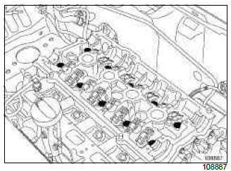
- the valve rockers (3),
- the hydraulic tappets (4).
Note: To prevent any risk of unpriming the hydraulic tappets make sure that they are vertical.

- Position the (Mot. 1672).
- Remove the (Mot. 1453).
II - OPERATION FOR REMOVAL OF PART CONCERNED

- Remove:
- the cylinder head bolts,
- the cylinder head.
- Mount the cylinder head on the cylinder head support (Mot. 1573).
- Remove the cylinder head gasket from the cylinder block.
REFITTING
I - REFITTING PREPARATION OPERATION
- parts always to be replaced: Cylinder head gasket.
- parts always to be replaced: cylinder head bolts.
WARNING
Do not scrape the joint faces of the aluminium, any damage caused to the joint face will result in a risk of leaks.
IMPORTANT
Wear goggles with side protectors for this operation.
IMPORTANT
Wear protective gloves during the operation.
WARNING
Do not allow this product to drip onto the paintwork.
Clean the cylinder head carefully to avoid any foreign bodies entering the oil return and supply pipes.
Failure to follow this advice could lead to the blocking of the various oil inlet galleries, which would quickly result in engine damage.
WARNING
To ensure proper sealing, the gasket surfaces must be clean, dry and not greasy (avoid any finger marks).
- Apply SUPER CLEANER FOR JOINT FACES (see ) (04B, Consumables - Products) on the parts to be cleaned (see Vehicle: Parts and consumables for the repair) (04B, Consumables - Products).
- Leave for approximately ten minutes.
- Remove residues with a wooden spatula.
- Finish cleaning the parts using a GREY ABRASIVE PAD.
- Use a ruler and set of feeler gauges to check that
there is no gasket face bow.
Maximum distortion: 0.05 mm
WARNING
No regrinding of the cylinder head is permitted.
- Test the cylinder head to detect any possible cracks using a cylinder head test tank.
- For the procedure of stripping down the cylinder head (see ) (Technical Note 6006A, 10A, Engine and peripherals).
- Position the pistons at mid-stroke to prevent any contact with the valves when refitting the camshafts.
- Be sure to degrease:
- the combustion side of the cylinder head,
- the combustion side of the cylinder block.

- Check that the centring dowel (5) is on the cylinder block.
- Set up tool (Mot. 104) (6) on the cylinder block.
II - REFITTING OPERATION FOR PART CONCERNED
- Fit a new cylinder head gasket.
- Refit the cylinder head.
WARNING
In order to ensure that the bolts are correctly tightened, use a syringe to remove any oil which may be in the cylinder head mounting holes.
WARNING
Do not oil the new bolts. Be sure to oil bolts being reused.

- Pretighten to torque and in order the cylinder head bolts (20 N.m).
- Check that all the cylinder head bolts are tightened to the correct torque of 20 N.m.
- Angle tighten in order the cylinder head bolts (240

