Renault Clio: Diesel injector: Configurations
K9K, and 750 or 752 or 766 or 768
- To configure the injectors, (see MR 394 Fault finding, Diesel Injection, Configuration and programming).
Diesel injector: Removal - Refitting
K9K, and 764 or 772
IMPORTANT
To avoid all risk of damage to the systems, apply the safety and cleanliness instructions and operation recommendations before carrying out any repair:
- (see 13B, Diesel injection, Diesel injection: Precautions for the repair, 13B-1),
- (see Vehicle: Precautions for the repair) (01D, Mechanical introduction).
REMOVING AN INJECTOR
I - REMOVAL PREPARATION OPERATION
- Switch off the ignition and wait 30 seconds before starting work on the injection system.
IMPORTANT
Use the diagnostic tool before any operation is carried out on the injection circuit to check:
- that the rail is not under pressure,
- that the fuel temperature is not too high.
Working on the circuit with the engine running is strictly forbidden.
- Disconnect the battery (see Battery: Removal - Refitting) (80A, Battery).
- Remove the engine cover.
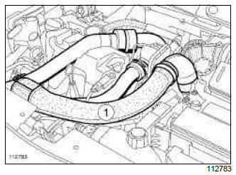
- Remove the air inlet sleeve (1).
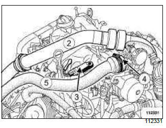
- Remove the turbocharging duct (2).
- Disconnect the inlet pressure sensor connector (3).
- Loosen the inlet duct clip (4).
- Move the air inlet duct (5) to one side.
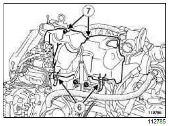
- Unclip the rail protector cover at (6).
- Remove:
- the bolts (7) from the rail protector cover,
- the rail protector cover,
- the dipstick.
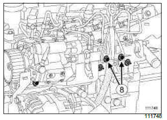
- Remove the bolts (8) of the dipstick duct on the injector rail protector.
- Move the dipstick duct to one side.
- Protect the alternator from fuel outflow.
- Clean the high pressure pipes between the rail and the injectors, as well as the fuel return pipe (see 13B, Diesel injection, Diesel injection: Precautions for the repair, 13B-1).
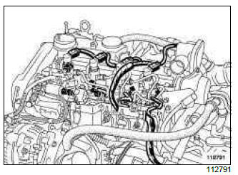
- Disconnect the electrical connector of the injector to be removed.
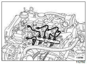
- Remove:
- the high pressure pipe union between the injector rail and the injector to be removed at the rail end,
- the high pressure pipe union between the injector rail and the injector to be removed at the injector end,
WARNING
Always hold the intermediate injector union in place with a wrench when loosening the high pressure pipes.
Do not damage the injector return nozzle.
- Remove the high pressure pipe concerned and discard it.
WARNING
To avoid any corrosion or damage, protect the areas on which fuel is likely to run.
WARNING
To prevent impurities from entering the circuit, place protective plugs on all fuel circuit components exposed to the open air.
- Insert the correct blanking plugs on the unions of:
- the injector fuel inlet,
- the injector rail fuel outlet.
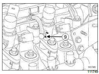
- Using a narrow, flat-blade screwdriver, push the lower bracket (9) of the retaining clip of the fuel return union on the injector towards the rocker cover.
WARNING
Do not use the screwdriver as a lever on the injector fuel return unions.
WARNING
Ensure that the clip is not completely removed from its housing, otherwise it may be damaged when the diesel return union is removed.
In the case where a clip has been completely removed from its housing, remove the injector concerned and replace the clip with a new clip (see 13B, Diesel injection, Diesel injector: Removal - Refitting, 13B-83).
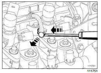
- Pushing the lower bracket of the retaining clip downwards, pull out the injector fuel return union.
- Fit suitable blanking plugs on:
- the fuel return union,
- the return fuel connector of the injector.
- Push the fuel return pipe on the injector to one side.
II - OPERATION FOR REMOVAL OF PART CONCERNED
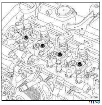
- Remove:
- the bolts on the injector bracket to be removed,
- the injector bracket,
- the spacer,
- the injector.
- Remove the heat protection washer.
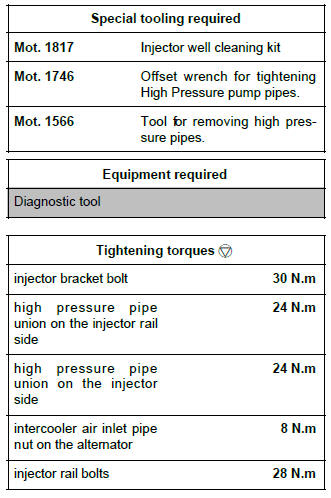
Note: If the heat protection washer is stuck at the bottom of the well, use the (Mot. 1817) (see Injector well cleaning tool: Use) (Technical Note 6040A, 13B, Diesel injection).
Note: If the injector is stuck in its well and cannot be removed, turn the injector by the retaining lugs on the injector bracket, using a 13 mm fork wrench.
- Fit the appropriate blanking plug on the injector's nose.
- If it is to be reused, keep the injector in a sealed plastic bag all the time it is removed.
- Take care not to allow impurities to enter the cylinder via the injector well.
- Block the opening with a clean cloth.
REFITTING AN INJECTOR
I - REFITTING PREPARATION OPERATION
- parts always to be replaced: injector seal.
- parts always to be replaced: High pressure pipe.
- Parts always to be replaced:
- any injector that has been opened, contrary to instructions,
- all retaining clips on the fuel return union on the damaged injector.
Cleaning parts
WARNING
It is strictly forbidden to clean the injectors with:
- a wire brush,
- an emery cloth,
- an ultrasonic cleaner.
- Always clean the well of the removed injector (see Injector well cleaning tool: Use) (Technical Note 6040A, 13B, Diesel injection).
- If reusing the removed injector:
- clean the injector using a wipe soaked in injector cleaning product or brake cleaner,
- if necessary, leave the injector nozzle to soak in injector cleaning product,
- wipe the injector with a new wipe,
- (see Vehicle: Parts and consumables for the repair) (04B, Consumables - Products) and (see 13B, Diesel injection, Diesel injection: Precautions for the repair, 13B-1).
II - REFITTING OPERATION FOR PART CONCERNED
- Remove the injector from its plastic bag.
WARNING
Do not remove the blanking plugs from each component until the last moment.
Also, do not remove the components from their packaging until they are to be fitted to the vehicle.
- Remove the blanking plug from the injector nose.
- Fit in order:
- a new fire-resistant washer at the bottom of the injector's well in the cylinder head,
- the injector,
- the spacer between the cylinder head and the injector bracket,
- the injector bracket,
- Finger tighten the injector bracket bolt.
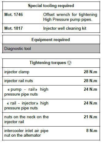
- Torque tighten the injector bracket bolt (30 N.m).
III - FINAL OPERATION
- Remove the blanking plugs from:
- the injector rail,
- the injector
WARNING
Before fitting a new high pressure pipe, lightly lubricate the nut threads with the oil from the applicator provided in the new parts kit.
Be careful not to allow oil into the high pressure pipe.
Do not lubricate high pressure pipes supplied without an applicator, as these high pressure pipes are self-lubricating.
- Fit a new high pressure pipe between the injector rail and the injector.
- Finger tighten the high pressure pipe unions, starting at the injector rail end.
- Torque tighten in order, using the (Mot. 1746) or
(Mot. 1566) :
- the high pressure pipe union on the injector rail side (24 N.m),
- the high pressure pipe union on the injector side (24 N.m).
- Remove the blanking plugs from:
- the fuel return union,
- the return fuel port of the injector.
- Push the retaining clip for the fuel return union on the injectors towards the front of the vehicle until it is in its original position.
- Clip the fuel return union on the injector.
WARNING
Check the condition of the seals on the fuel return unions on the injectors. Check that they are not cut or crushed, and have not come out of their grooves. Replace the diesel return pipe assembly if one of its components is damaged.
- Replace the fuel return pipe assembly if one of its components is damaged.
- Connect the injector's electrical connector.
- Refit:
- the dipstick,
- the rail protector cover,
- the air duct between the intercooler and the cut-out valve.
- Loosen the intercooler air inlet pipe nut on the alternator.
- Fit the air duct between the turbocharger and the intercooler air inlet pipe.
- Snap the air duct to the turbocharger and to the air pipe at the intercooler inlet.
- Tighten the bolt of the air duct on the rocker cover.
- Torque tighten the intercooler air inlet pipe nut on the alternator (8 N.m).
- Refit the engine cover.
- Reprime the fuel circuit using the manual priming pump.
- Connect the battery (see Battery: Removal - Refitting) (80A, Battery).
- Before restarting the engine, use the Diagnostic tool to clear any faults stored by the injection computer.
- Check that there are no diesel leaks:
- check the sealing after repair (see 13B, Diesel injection, High pressure pipe: Check, 13B- 99),
- let the engine run at idle speed until the engine cooling fan starts to operate,
- accelerate several times at no load,
- check that there is no diesel fuel escaping.
- Use the Diagnostic tool to check that there are no stored faults, and clear them if necessary.
REMOVING ALL FOUR INJECTORS
I - REMOVAL PREPARATION OPERATION
- Switch off the ignition and wait 30 seconds before starting work on the injection system.
IMPORTANT
Use the diagnostic tool before any operation is carried out on the injection circuit to check:
- that the rail is not under pressure,
- that the fuel temperature is not too high.
Working on the circuit with the engine running is strictly forbidden.
- Disconnect the battery (see Battery: Removal - Refitting) (80A, Battery).
- Remove the engine undertray.
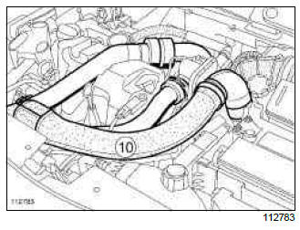
- Remove the air inlet sleeve (10).
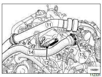
- Remove the turbocharging duct (11).
- Disconnect the inlet pressure sensor connector (12).
- Loosen the inlet duct clip (13).
- Move the air inlet duct (14) to one side.
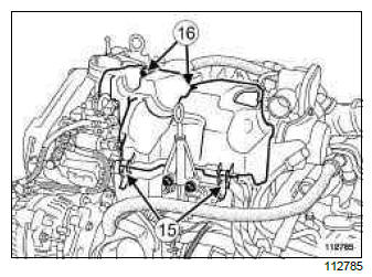
- Unclip the rail protector cover at (15).
- Remove:
- the bolts (16) from the rail protector cover,
- the rail protector cover,
- the dipstick.
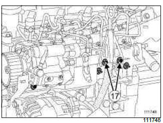
- Remove the bolts (17) of the dipstick duct on the injector rail protector.
- Move the dipstick duct to one side.
- Protect the alternator from fuel outflow.
- Clean the high pressure pipes between the rail and the injectors, as well as the fuel return pipe (see 13B, Diesel injection, Diesel injection: Precautions for the repair, 13B-1).
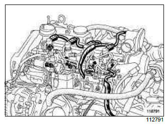
- Disconnect the injector electrical connectors.
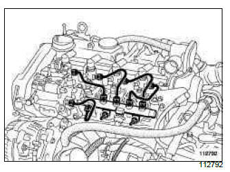
- Remove:
- the high pressure pipe unions between the injector rail and the injectors at the rail end,
- the high pressure pipe unions between the injector rail and the injectors at the injector end,
WARNING
Always hold the intermediate injector union in place with a wrench when loosening the high pressure pipes.
Do not damage the injector return nozzle.
- Remove the high pressure pipes and discard.
WARNING
To avoid any corrosion or damage, protect the areas on which fuel is likely to run.
WARNING
To prevent impurities from entering the circuit, place protective plugs on all fuel circuit components exposed to the open air.
- Insert the correct blanking plugs on the unions of:
- the injector fuel inlet,
- the injector rail fuel outlet.
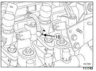
- Using a narrow flat-blade screwdriver, push the lower brackets (18) of the fuel return union retaining clips on the injectors towards the rocker cover.
WARNING
Do not use the screwdriver as a lever on the injector fuel return unions.
WARNING
Ensure that the clip is not completely removed from its housing, otherwise it may be damaged when the diesel return union is removed.
In the case where a clip has been completely removed from its housing, remove the injector concerned and replace the clip with a new clip (see 13B, Diesel injection, Diesel injector: Removal - Refitting, 13B-83).
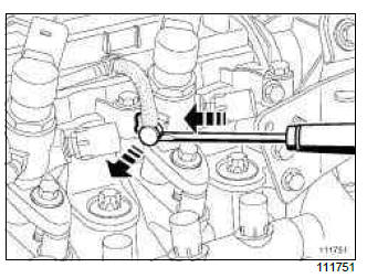
- Pushing the lower brackets of the retaining clips downwards, pull out the fuel return unions on the injectors.
- Fit suitable blanking plugs on:
- the fuel return unions,
- the fuel return openings on the injectors.
- Push the injector fuel return pipe to one side.
II - OPERATION FOR REMOVAL OF PART CONCERNED
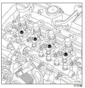
- Remove:
- the injector clamp bolts,
- the injector clamps,
- the spacers,
- the injectors.
- Remove the heat protection washers.
Note: If the compression washer is stuck at the bottom of the well, use the (Mot. 1817) (see Injector well cleaning tool: Use) (Technical Note 6040A, 13B, Diesel injection).
Note: If the injector is stuck in its well and cannot be removed, turn the injector by the retaining lugs on the injector bracket, using a 13 mm fork wrench.
- Fit the correct blanking plugs on the injector noses.
- If they are to be reused, keep the injectors in a sealed plastic bag all the time they are removed.
- Take care not to allow impurities to enter the cylinders via the injector wells.
- Block the openings using clean cloths.
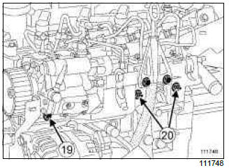
- Remove:
- the bolt (19) and the nuts (20) of the rail protector,
- the rail protector.
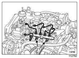
- Loosen the injector rail nuts (21) by a few turns.
Note: The injector rail must be loose.
REFITTING THE FOUR INJECTORS
I - REFITTING PREPARATION OPERATION
- parts always to be replaced: injector seal.
- parts always to be replaced: High pressure pipe.
- Parts always to be replaced:
- any injector that has been opened, contrary to instructions,
- all retaining clips on the fuel return union on the damaged injector.
Cleaning parts
WARNING
It is strictly forbidden to clean the injectors with:
- a wire brush,
- an emery cloth,
- an ultrasonic cleaner.
- Always clean the well of the removed injectors (Mot.1817) (see Injector well cleaning tool: Use) (Technical Note 6040A, 13B, Diesel injection).
- If reusing the removed injector:
- clean the injector using a wipe soaked in injector cleaning product or brake cleaner,
- if necessary, leave the injector nozzle to soak in injector cleaning product,
- wipe the injector with a new wipe,
- (see ) (04B, Consumables - Products) and (see 13B, Diesel injection, Diesel injection: Precautions for the repair, 13B-1).
II - REFITTING OPERATION FOR PART CONCERNED
- Take the injectors out of their plastic bag.
WARNING
Do not remove the blanking plugs from each component until the last moment.
Also, do not remove the components from their packaging until they are to be fitted to the vehicle.
- Remove the blanking plug from the injector noses.
- Fit in order:
- new compression washers at the bottom of the injector wells in the cylinder head,
- the injectors,
- the spacers between the cylinder head and the injector brackets,
- the injector brackets.
- Finger tighten the injector bracket bolts.
- Torque tighten the injector bracket bolts (30 N.m).
III - FINAL OPERATION
- Remove the blanking plugs from:
- the injector rail,
- the injectors.
WARNING
Before fitting a new high pressure pipe, lightly lubricate the nut threads with the oil from the applicator provided in the new parts kit.
Be careful not to allow oil into the high pressure pipe.
Do not lubricate high pressure pipes supplied without an applicator, as these high pressure pipes are self-lubricating.
- Fit the new high pressure pipes between the injector rail and the injectors.
- Finger tighten the high pressure pipe unions, starting at the injector rail end.
- Torque tighten the injector rail bolts (28 N.m).
- Torque tighten in order, using the (Mot. 1746) or
(Mot. 1566) :
- the high pressure pipe unions on the injector rail side (24 N.m),
- the high pressure pipe unions on the injector side (24 N.m).
- Remove the blanking plugs from:
- the fuel return unions,
- the fuel return openings on the injectors.
- Push the retaining clips for the fuel return unions on the injectors towards the front of the vehicle until they are in their original positions.
- Clip the fuel return unions on the injectors.
WARNING
Check the condition of the seals on the fuel return unions on the injectors. Check that they are not cut or crushed, and have not come out of their grooves. Replace the diesel return pipe assembly if one of its components is damaged.
- connect the electrical connectors to the injectors.
- Refit:
- the rail protector,
- the dipstick guide tube,
- the dipstick,
- the rail protector cover,
- the air duct between the intercooler and the cut-out valve.
- Loosen the intercooler inlet air pipe nut on the alternator.
- Fit the air duct between the turbocharger and the intercooler air inlet pipe.
- Snap the air duct to the turbocharger and to the air pipe at the intercooler inlet.
- Refit the air duct bolt on the rocker cover.
- Torque tighten the intercooler air inlet pipe nut on the alternator (8 N.m).
- Reprime the fuel circuit using the manual priming pump.
- Connect the battery (see Battery: Removal - Refitting) (80A, Battery).
- Before restarting the engine, use the Diagnostic tool to clear any faults stored by the injection computer.
- Check that there are no diesel leaks:
- check the sealing after repair (see 13B, Diesel injection, High pressure pipe: Check, 13B- 99),
- let the engine run at idle speed until the engine cooling fan starts to operate,
- accelerate several times at no load,
- check that there are no diesel leaks.
- Use the Diagnostic tool to check that there are no stored faults, and clear them if necessary.
- Refit the engine cover.
K9K, and 750 or 752 or 766 or 768
IMPORTANT
To avoid all risk of damage to the systems, apply the safety and cleanliness instructions and operation recommendations before carrying out any repair:
- (see 13B, Diesel injection, Diesel injection: Precautions for the repair, 13B-1),
- (see Vehicle: Precautions for the repair) (01D, Mechanical introduction).
Note: Vehicles equipped with the K9K*768 engine may or may not be equipped with an intercooler.
REMOVAL
I - REMOVAL PREPARATION OPERATION
- Remove the front engine cover.
- Disconnect the battery (see Battery: Removal - Refitting) (80A, Battery).
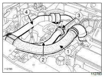
- Remove the air inlet duct (1).
- Disconnect the turbocharger pressure sensor connector (2).
K9K, and 750 or 766 or 768
- Loosen the clip of the air duct (3) between the intercooler and the damper valve.
- Move aside the air duct between the intercooler and the damper valve.
- Remove the stainless steel pipe (4) between the turbocharger and the intercooler.
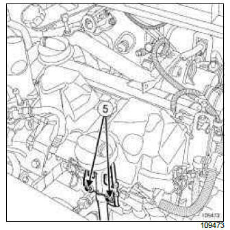
- Remove the dipstick bolts (5).
- Put the dipstick to one side.
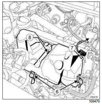
- Unclip the rail protector by the clips (6).
- Remove:
- the engine cover bracket (7) on the flywheel end,
- the rail protector bolt (8),
- the rail protector.
- Disconnect:
- the heater plugs,
- injector connectors no. 3 and no. 4,
- injector connectors no. 1 and no. 2.
WARNING
Do not use the screwdriver as a lever on the injector fuel return unions.
WARNING
Ensure that the clip is not completely removed from its housing, otherwise it may be damaged when the diesel return union is removed.
In the case where a clip has been completely removed from its housing, remove the injector concerned and replace the clip with a new clip (see 13B, Diesel injection, Diesel injector: Removal - Refitting, 13B-83).
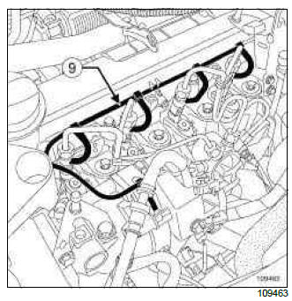
- Disconnect the injector diesel return pipe (9).
WARNING
To prevent impurities from entering the circuit, place protective plugs on all fuel circuit components exposed to the open air.
- Fit plugs into the openings.
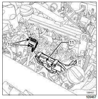
- Disconnect the high pressure pump electrical connectors (10).
- Remove the bolts of the neck (11) of the spherical injector rail.
- Move aside the electrical wiring with the neck.
- Loosen the injector rail nuts by several turns.
- Remove the clips connecting the high pressure pipes.
WARNING
Always hold the intermediate injector union in place with a wrench when loosening the high pressure pipes.
Do not damage the injector return nozzle.
- Undo:
- the high pressure pipe nut at the injector end using the (Mot. 1746),
- the high pressure pipe nut at the injector rail end using the (Mot. 1746).
- Fit blanking plugs into the openings.
II - OPERATION FOR REMOVAL OF PART CONCERNED
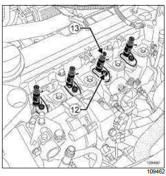
- Loosen the injector bracket (12).
- Remove the injector (13).
- If reusing an injector, always mark a removed injector in relation to its cylinder.
Note: an injector corresponds to a cylinder.
- Remove the heat protection washer.
Note: If the heat protection washer is stuck at the bottom of the well, use the (Mot. 1817) (see Injector well cleaning tool: Use) (Technical Note 6040A, 13B, Diesel injection).
REFITTING
I - REFITTING PREPARATION OPERATION
- parts always to be replaced: injector seal.
- parts always to be replaced: High pressure pipe.
Cleaning parts
WARNING
It is strictly forbidden to clean the injectors with:
- a wire brush,
- an emery cloth,
- an ultrasonic cleaner.
- Always clean the well of the removed injector (see Injector well cleaning tool: Use) (Technical Note 6040A, 13B, Diesel injection).
- If reusing the removed injector:
- clean the injector using a wipe soaked in injector cleaning product or brake cleaner,
- if necessary, leave the injector nozzle to soak in injector cleaning product,
- wipe the injector with a new wipe,
- (see ) (04B, Consumables - Products) and (see 13B, Diesel injection, Diesel injection: Precautions for the repair, 13B-1).
II - REFITTING OPERATION FOR PART CONCERNED
WARNING
Do not remove the caps from each component until the last moment.
- If removing the four injectors, loosen the nuts of the injector rail by a few turns (the rail should be loose).
- Replace the compression washer with a new one.
- Position the injector.
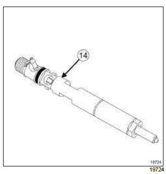
Note: If one or more injectors are replaced, note the alphanumeric code (C2I) (14) and the cylinder on which it is fitted.
- Torque tighten the injector clamp (28 N.m).
III - FINAL OPERATION
WARNING
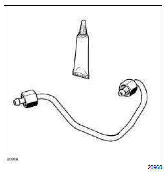
Before fitting a new high pressure pipe, lightly lubricate the nut threads with oil from the applicator provided with the new part.
Be careful not to allow oil into the high pressure pipe.
Do not lubricate high pressure pipes supplied without an applicator; these pipes are self-lubricating.
WARNING
Do not remove the blanking plugs from each component until the last moment.
Also, do not remove the components from their packaging until they are to be fitted to the vehicle.
- Position the high pressure pipe olive:
- in the high pressure inlet taper of the injector,
- in the high pressure outlet taper of the rail.
- Fit without tightening the high pressure pipe nuts by hand, starting with the nut at the injector end.
- Slightly pretighten the high pressure pipe nuts.
Note: The assembly order of the " rail - injector " high pressure pipes is not important.
- Mount a new clip provided with the new high pressure pipe.
- If removing the four injectors, torque tighten the injector rail nuts (28 N.m).
- Tighten to torque and in order the " pump - rail "
high pressure pipe nuts (24 N.m) :
- high pressure pump end,
- rail end.
- Tighten to torque and in order the " rail - injector "
high pressure pipe nuts (24 N.m) :
- injectors end,
- rail end.
Note: Tighten each pipe fully before moving on to the next pipe.
- Refit the neck on the injector rail.
- Tighten to torque the nuts on the neck on the injector rail (21 N.m).
WARNING
Check the condition of the seals on the fuel return unions on the injectors. Check that they are not cut or crushed, and have not come out of their grooves. Replace the diesel return pipe assembly if one of its components is damaged.
- Connect:
- the injector diesel fuel return pipe,
- the connectors to injectors no. 1 and no. 2,
- the connectors to injectors no. 3 and no. 4,
- the heater plugs.
- Refit:
- the rail protector,
- the front engine cover bracket on the flywheel end.
- Clip on the rail protector.
K9K, and 750 or 766 or 768
- Loosen the intercooler inlet air pipe nut on the alternator.
- Fit the air duct on the turbocharger and on the intercooler inlet air pipe.
- Tighten the bolt of the air duct on the rocker cover.
- Torque tighten the intercooler inlet air pipe nut on the alternator (8 N.m).
- Tighten the clip of the air duct between the intercooler and the damper valve.
- Connect the turbocharger pressure sensor connector.
- Refit the air inlet duct.
- Connect the battery (see Battery: Removal - Refitting) (80A, Battery).
- Program the alphanumeric code (C2I) for the replaced injector(s) using the Diagnostic tool (see Fault finding - Replacement of components) (13B, Diesel injection).
- Check that there are no diesel leaks:
- run the engine until the fan starts,
- accelerate several times at no load,
- switch off the ignition,
- check that there is no diesel fuel escaping.
- Refit the engine cover.

