Renault Clio: Injector rail: Removal - Refitting
K9K, and 764 or 772
WARNING
Before starting work on the vehicle, have to hand:
- a new blanking plug kit (part no. 77 01 476 857),
- cleaning wipes (part no. 77 11 211 707),
- cleaning product (part no. 77 11 224 188).
WARNING
Parts always to be replaced:
- all the high pressure pipes which have been removed.
REMOVAL
I - REMOVAL PREPARATION OPERATION
- Position the vehicle on a lift (see Vehicle: Towing and lifting) (MR 392, 02A, Lifting equipment).
- Switch off the ignition and wait 30 seconds before starting work on the injection system.
IMPORTANT
Before carrying out any work on the injection system, check using the Diagnostic tool :
- that the rail is not under pressure,
- that the fuel temperature is not too high.
It is essential to respect the safety and cleanliness advice whenever work is carried out on this system (see 13B, Diesel injection, Diesel injection: Precautions for the repair, 13B-1).
- Disconnect the battery (see Battery: Removal - Refitting) (MR 392, 80A, Battery).
- Remove the engine cover.
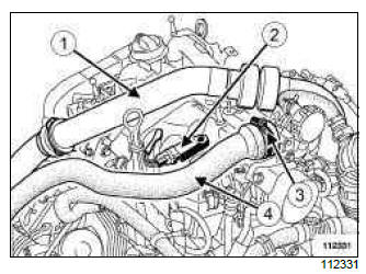
- Remove the upper section (1) of the turbocharging duct.
- Disconnect the inlet air pressure sensor (2)
- Loosen the clip (3).
- Move the inlet duct to one side (4).
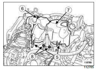
- Unclip the clips (5) from the injector rail protector cover.
- Remove:
- the injector rail protector cover mounting bolt (6),
- the injection rail protector cover (7),
- the dipstick,
- the dipstick tube (8) mounting bolts.
- Move the dipstick duct to one side.
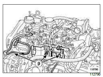
- Remove:
- the injector rail protector support mounting bolts (9),
- the injector rail protector mounting.
- Protect the alternator from fuel outflow.
- Pour cleaning product into a container.
IMPORTANT
Wear protective gloves when using cleaning product.
- Soak the brush with cleaning product, then clean the
unions:
- of the high pressure pipes between the injector rail and the injectors
- of the high pressure pipe between the pump and the injection rail.
- Blast the cleaned areas with compressed air, then wipe them with new cleaning cloths.
IMPORTANT
Wear protective glasses.
WARNING
Do not blow compressed air once the fuel circuit is open, otherwise impurities may enter the system.
Use wipes if necessary.
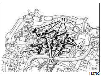
- Undo:
- the nut securing the four high pressure pipes between the injection rail and the injector at the rail end (10),
- the nut securing the high pressure pipes between the injection rail and the injector at the injector end (11),
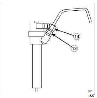
WARNING
When the high pressure pipe unions (14) on the injector holder have been loosened, always hold the rod filter retaining nut (13) with a lock wrench.
- Remove the four high pressure pipes (12) and discard them.
Note: Make preparations for fuel outflow. Clean with new cloths.
- Fit the blanking plugs.
- Remove the high pressure pipe between the high pressure pump and the injection rail and discard it.
Note: Hold the intermediate nut between the pump-rail pipe and the high pressure pump using a lock wrench.
Note: Make preparations for fuel outflow. Clean with new cloths.
Insert the correct blanking plugs.
II - REMOVAL OF PART CONCERNED
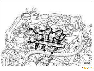
- Remove:
- the injector rail mounting nuts (16),
- the injector rail.
WARNING
If the injection rail is to be reused, keep it in a sealed plastic bag all the time it is disconnected.
REFITTING
I - REFITTING PREPARATION OPERATION
WARNING
Remove the blanking plugs only before reconnecting the fuel circuit pipes.
The plugs are single-use only. Do not reuse them, and discard the kit once opened.
- Take the injector rail out of its plastic bag
WARNING
If an injector rail is being replaced, only remove the new one from its original packaging when it is about to be fitted.
II - REFITTING PART CONCERNED
- Fit the injector rail.
- Finger tighten the injection rail mounting bolts (the injection rail should be loose).
III - FINAL OPERATION.
- Remove the blanking plugs from:
- the high pressure pump,
- the injection rail fuel inlet opening.
- Fit a new high pressure pipe between the injector rail and the high pressure pump.
Note: If the new pipe kit does not contain an applicator, lubrication of the pipe threads will be unnecessary (as they are self-lubricating pipes).
- Finger tighten the high pressure pipe nuts until they make contact.
- Remove the blanking plugs from:
- the rail injector fuel return openings,
- the injector fuel inlet.
- Fit the new high pressure pipes between the rail and the injectors.
Note: If the new pipe kit does not contain an applicator, lubrication of the pipe threads will be unnecessary (as they are self-lubricating pipes).
- Finger tighten the high pressure pipe nuts until they make contact.
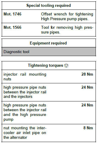
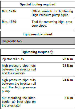
- Torque tighten:
- the injector rail mounting nuts (28 Nm),
- the high pressure pipe nuts between the injector
rail and the injectors (24 Nm) using the (Mot.
1746) or (Mot. 1566), starting on the injector side,
- the high pressure pipe nuts between the injector rail and the high pressure pump (24 Nm) using the (Mot. 1746) or (Mot. 1566), starting on the high pressure pump side.
- Refit:
- the injector rail protector mounting,
- the mounting bolts from the injection rail protector mounting,
- the dipstick duct mounting bolts.
- the dipstick,
- the injector rail protector cover,
- injection rail protector cover mounting bolts,
- Refit the air inlet duct and tighten the mounting clip.
- Connect the inlet air pressure sensor
- Loosen the mounting nut securing the intercooler
air inlet pipe to the alternator,
- fit the air duct between the turbocharger and the intercooler air inlet pipe,
- lock the air duct onto the turbocharger and the intercooler air inlet pipe.
- tighten the air duct bolt on the rocker cover,
- torque tighten the nut mounting the intercooler air inlet pipe on the alternator (8 Nm).
- Reprime the fuel circuit.
- Connect the battery (see Battery: Removal - Refitting) (MR 392, 80A, Battery).
- Confirm that there is no diesel fuel leak:
- check the sealing after repair (see 13B, Diesel injection, High pressure pipe: Check, 13B- 99),
- let the engine run at idle speed until the engine cooling fan starts to operate,
- accelerate several times at no load,
- check that there are no diesel leaks.
- Use the Diagnostic tool to check for stored faults.
Clear them if necessary.
K9K, and 750 or 752 or 766 or 768
WARNING
Before starting work on the vehicle, have to hand:
- a new blanking plug kit (part no. 77 01 206 804),
- cleaning cloths (part no. 77 11 211 707),
- cleaning product (part no. 77 11 224 188).
WARNING
Parts always to be replaced:
- all the high pressure pipes which have been removed.
Note: Vehicles equipped with the K9K*768 engine may or may not be equipped with an intercooler.
REMOVAL
I - REMOVAL PREPARATION OPERATION
- Position the vehicle on a lift (see Vehicle: Towing and lifting) (MR 392, 02A, Lifting equipment).
- Switch off the ignition and wait 30 seconds before starting work on the injection system.
IMPORTANT
Before carrying out any work on the injection system, check using the Diagnostic tool :
- that the rail is not under pressure,
- that the fuel temperature is not too high.
It is essential to respect the safety and cleanliness advice whenever work is carried out on this system (see 13B, Diesel injection, Diesel injection: Precautions for the repair, 13B-1).
- Disconnect the battery (see Battery: Removal - Refitting) (MR 392, 80A, Battery).
- Remove the front engine cover.
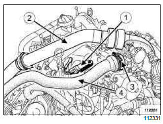
- Disconnect the inlet air pressure sensor (1).
K9K, and 750 or 766 or 768
- Remove the upper section (2) of the turbocharging duct.
- Loosen the clip (3).
- Move the inlet duct to one side (4).
- Remove:
- the dipstick,
- the dipstick duct bolts.
- Move the dipstick duct to one side.
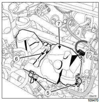
- Unclip the clips (5) from the injector rail protector cover.
- Remove:
- the injector rail protector cover bolt (6),
- the injector rail protector cover (7),
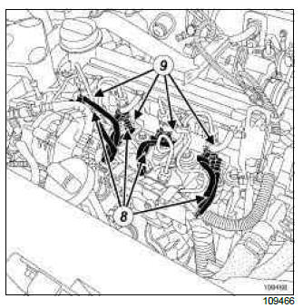
- Disconnect the connectors from the injectors (8) and the heater plugs (9).
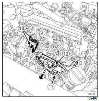
- Disconnect:
- the connectors (10) from the fuel flow actuator and the diesel temperature sensor,
- the pressure sensor (11) from the spherical injector rail,
- Move the electric wiring harness and neck to the side as shown by the arrow.
- Remove the mountings from the neck (12) fixed on the spherical rail.
- Protect the alternator from fuel outflow.
- Pour cleaning product into a container.
IMPORTANT
Wear protective gloves when using cleaning product.
- Soak the brush with cleaning product, then clean the
unions:
- on the high-pressure pipes between the injector rail and the injectors,
- of the high pressure pipe between the pump and the injection rail.
- Blast the cleaned areas with compressed air, then wipe them with new cleaning cloths.
IMPORTANT
Wear protective glasses.
WARNING
To prevent impurities from entering, once the fuel circuit is opened, it must not be blasted with compressed air. Use cloths if necessary.
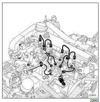
- Remove the clips between the high pressure pipes.
- Undo:
- the nut securing the high pressure pipes between the injection rail and the injector,
- Remove the four high pressure pipes and discard.
Note: Make preparations for fuel outflow. Clean with new cloths.
- Insert the blanking plugs.
- Remove the high pressure pipe between the high pressure pump and the injector rail (13).
Note: Make preparations for fuel outflow. Clean with new cloths.
- Insert the blanking plugs.
II - REMOVAL OF PART CONCERNED
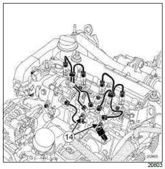
- Remove:
- the nuts (14) from the injector rail,
- the injector rail.
WARNING
If the injector rail is to be reused, keep it in a sealed plastic bag all the time it is disconnected.
REFITTING
I - REFITTING PREPARATION OPERATION
WARNING
Only remove the blanking plugs immediately before connecting the fuel circuit pipes.
The plugs are single-use. Do not reuse them, and discard the whole kit once opened.
- Take the injector rail out of its plastic bag.
WARNING
If an injector rail is being replaced, only remove the new one from its original packaging when it is about to be fitted.
II - REFITTING PART CONCERNED
- Fit the injector rail.
- Screw on the injector rail bolts without tightening them (the rail should be loose).
III - FINAL OPERATION
- Remove the blanking plugs from:
- the high pressure pump,
- from the fuel inlet port of the injector rail.
- Fit a new high-pressure pipe between the injection rail and the high-pressure pump.
Note: If the new pipe kit does not contain an applicator, lubrication of the pipe threads will be unnecessary (as they are self-lubricating pipes).
- Screw on the high pressure pipe nuts by hand until contact is made, but without tightening them.
- Remove the blanking plugs from:
- from the fuel outlet ports of the injector rail,
- from the fuel inlet of the injector.
- Fit the new high-pressure pipes between the rail and the injectors.
Note: If the new pipe kit does not contain an applicator, lubrication of the pipe threads will be unnecessary (as they are self-lubricating pipes).
- Screw on the high pressure pipe nuts by hand until contact is made, but without tightening them.
- Torque tighten:
- the injector rail nuts (28 N.m),
- the high pressure pipe nuts between the injector rail and the injectors (24 N.m) using the (Mot.1746) or (Mot. 1566), starting on the injector side,
- the high pressure pipe nuts between the injector rail and the high pressure pump (24 N.m) using the (Mot. 1746) or (Mot. 1566), starting on the high pressure pump side.
- Refit:
- the wiring harness with the neck,
- the channel mountings,
- the dipstick duct bolts,
- the dipstick,
- the injector rail protector cover,
- the injector rail protector cover bolt.
- Connect the electrical connectors.
- Refit the air inlet duct and tighten the mounting clip.
- Connect the inlet air pressure sensor.
K9K, and 750 or 766 or 768
- Loosen the intercooler inlet air pipe nut on the alternator.
- Fit the air duct between the turbocharger and the intercooler inlet air pipe.
- Lock the air duct onto the turbocharger and the intercooler inlet air pipe.
- Tighten the bolt of the air duct on the rocker cover.
- Torque tighten the nut mounting the intercooler air inlet pipe on the alternator (8 N.m).
- Re-prime the fuel circuit.
- Connect the battery (see Battery: Removal - Refitting) (MR 392, 80A, Battery).
- Check that there are no diesel leaks:
- check the sealing after repair (see 13B, Diesel injection, High pressure pipe: Check, 13B- 99),
- let the engine run at idle speed until the engine cooling fan starts to operate,
- accelerate several times at no load,
- check that there are no diesel leaks.
- Use the Diagnostic tool to check for stored faults.
Clear them if necessary.
Rail pressure sensor: Removal - Refitting
K9K, and 764 or 772
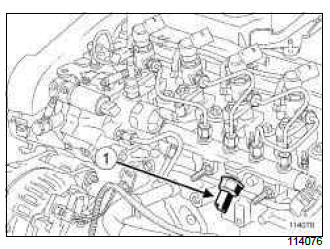
The injector rail pressure sensor (1) cannot be separated from the injector rail.
In the event of a fault on the rail pressure sensor, replace the "rail pressure sensor - injector rail and high pressure pipes" assembly (see 13B, Diesel injection, Injector rail: Removal - Refitting, 13B-64).
K9K, and 750 or 752 or 766 or 768
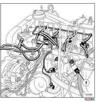
- The pressure sensor (1) cannot be removed from
the spherical injector rail.
If the pressure sensor is faulty, replace the " pressure sensor - high pressure pipes and rail " assembly (see 13B, Diesel injection, Injector rail: Removal - Refitting, 13B-64).

