Renault Clio: K9K, and Right-hand Drive

REMOVAL
I - REMOVAL PREPARATION OPERATION
- Position the vehicle on a two-post lift (see Vehicle: Towing and lifting) (MR 392, 02A, Lifting equipment).
- Disconnect the battery (see Battery: Removal - Refitting) (MR 392, 80A, Battery).
- Remove:
- the engine cover,
- the engine undertray,
- the scuttle panel grille (see Scuttle panel grille: Removal - Refitting) (MR 393, 56A, Exterior equipment),
- the scoop under the scuttle panel grille (see Scoop under the scuttle panel grille: Removal - Refitting) (MR 393, 56A, Exterior equipment),
- the non-return valve on the servo,
- the master cylinder (see 37A, Mechanical component controls, Master cylinder: Removal - Refitting, 37A-2),
- the lower cover strip,
- the dashboard side panel.

- Remove:
- the bolts (1),
- the lower cover (2), disconnecting the various connectors.
- the master cylinder (see 37A, Mechanical component controls, Clutch master cylinder: Removal - Refitting, 37A-107),
- the engine tie-bar (see Lower engine tie-bar: Removal - Refitting) (MR 392, 19D, Engine mounting).
- Remove the sub-frame bolts to fit the tool as shown below.
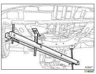
- Position the (Mot. 1672).

- Remove:
- the lifting eye bolt,
- the lifting eye (5),
- the EGR tube bolt,
- the EGR tube (6),
- the right-hand suspended mounting support (7) using only the (Mot. 1672) (see Right-hand suspended engine mounting: Removal - Refitting) (MR 392, 19D, Engine mounting).
- Lower the engine as much as possible using the (Mot. 1672).
II - OPERATION FOR REMOVAL OF PART CONCERNED

- Remove:
- the double safety connecting shaft (8) from between the brake servo pushrod and the brake pedal, and, after tilting the connecting shaft upwards, move ring (9) using a flat-blade screwdriver.
- the brake servo nuts (10),
- the brake servo.
Note: To pass the servo between the bulkhead and the engine, the pushrod must be oriented towards the bottom, with the engine slightly pulled forward.
REFITTING
I - REFITTING PREPARATIONS OPERATION

- Check that the brake servo seal (11) is present; replace the seal if it is faulty.
- The shaft connecting the brake servo pushrod and the brake pedal must be replaced every time it is removed.

- Before refitting, check that the dimension: (X1) = 128 mm.
II - REFITTING OPERATION FOR PART CONCERNED
- Refit:
- the brake servo,
- the brake servo nuts.
- The shaft connecting the brake servo pushrod and the brake pedal must be refitted from right to left, and from top to bottom.
- Torque tighten the brake servo nuts (21 Nm).
III - FINAL OPERATION.
- Refit:
- the right-hand suspended mounting support (see Right-hand suspended engine mounting: Removal - Refitting) (MR 392, 19D, Engine mounting),
- the EGR tube,
- the EGR tube bolt,
- the lifting eye,
- the lifting eye bolt.
- Remove the (Mot. 1672).
- Refit:
- the sub-frame bolts,
- the engine tie-bar (see Lower engine tie-bar: Removal - Refitting) (MR 392, 19D, Engine mounting),
- the master cylinder (see 37A, Mechanical component controls, Clutch master cylinder: Removal - Refitting, 37A-107),
- the master cylinder (see 37A, Mechanical component controls, Master cylinder: Removal - Refitting, 37A-2),
- the non-return valve on the servo,
- the scoop under the scuttle panel grille (see Scoop under the scuttle panel grille: Removal - Refitting) (MR 393, 56A, Exterior equipment),
- the scuttle panel grille (see Scuttle panel grille: Removal - Refitting) (MR 393, 56A, Exterior equipment),
- the engine undertray,
- the engine cover.
- Torque tighten the sub-frame bolts (105 Nm).
- Bleed:
- the clutch circuit (see 37A, Mechanical component controls, Clutch circuit: Bleed, 37A- 100),
- the brake circuit (see 30A, General information, Braking circuit: Bleed, 30A-4).
- Adjust:
- the brake switch (see 37A, Mechanical component controls, Brake pedal switch: Removal - Refitting, 37A-79),
- the clutch switch (see Clutch pedal position sensor: Removal - Refitting).
- Check that the connecting shaft between the brake servo pushrod and the brake pedal is locked in place.
- Refit:
- the lower cover and connect the various connectors,
- the lower cover bolts,
- the dashboard side panel,
- the lower cover strip,
- Connect the battery (see Battery: Removal - Refitting) (MR 392, 80A, Battery).
READ NEXT:
 D4F, and Left-hand Drive
REMOVAL
I - REMOVAL PREPARATION OPERATION
Put the vehicle on a two-post lift (see Vehicle: Towing and lifting).
Disconnect the battery (see Battery: Removal - Refitting).
Remove:
the non-ret
K4J or K4M, and Right-hand Drive
REMOVAL
I - REMOVAL PREPARATION OPERATION
Position the vehicle on a two-post lift (see Vehicle:
Towing and lifting) (MR 392, 02A, Lifting equipment).
Disconnect the battery (see Battery: Removal
D4F, and Right-hand Drive
REMOVAL
I - REMOVAL PREPARATION OPERATION
Position the vehicle on a two-post lift (see Vehicle:
Towing and lifting) (MR 392, 02A, Lifting equipment).
Disconnect the battery (see Battery: Removal
SEE MORE:
Heater matrix: Removal - Refitting
LEFT-HAND DRIVE
REMOVAL
I - REMOVAL PREPARATION OPERATION
Place hose clamps (Ms. 583) on the heater matrix hoses at (1).
Remove:
the heater matrix hose clips,
the heater matrix hoses,
the centre console (see Centre console: Removal
- Refitting) (MR 393, 57A, Interior equipment).
K4J or K4M
IMPORTANT
Consult the safety and cleanliness advice and operation
recommendations before carrying out any
repair (see 88A, Wiring harness, Wiring: Precautions
for the repair, 88A-5).
WARNING
To prevent damage to the wiring harness when
refitting, observe the original routing.
REMOVAL
I - REMOVAL PR
© 2016-2025 Copyright Renault Clio Owners Club
